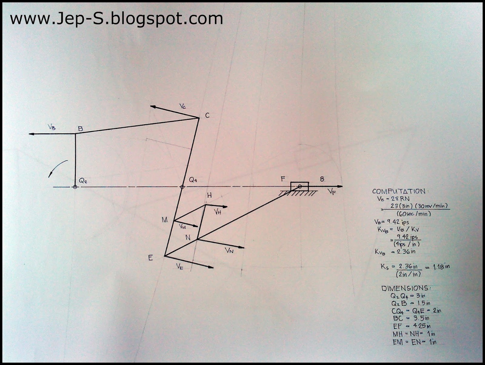
Here's my third plate. Like my second plate, it's about Velocity Analysis. I made this plate right after drawing the second one. It took me 2.5 hours to completely finish the plate. I had a hard time drawing it because the instantaneous axis of the links are too far, so I have to use a big compass. Here's the compass used by my classmate while making this plate.
Drawing after the cut.
Here's my third plate.
Check out the CAD version.
Showing posts with label Kinematics. Show all posts
Thursday, August 12, 2010
Tuesday, August 10, 2010
Kinematics - Resolution and Composition (Plate #2)
My second plate is about Velocity Analysis using the resolution and composition method. Velocity analysis is a graphical technique used for the determination of the velocities of the parts of a mechanical device, specially those of a plane mechanism with rigid component links. It was the first lesson on my Kinematics class and my third plate is also about velocity analysis using the instantaneous axis method.
The drawing itself is not that hard but you need to be very careful in executing the steps. Analyzing the problem is much more difficult. The more complex the linkage are the harder it will be. My second plate isn't that complicated but it took me about 3 hours just to finish this plate and I hope I will get a high grade on it.
Drawing after the cut.
Here's my second plate.
Q2BBCQ4EFPS is a compound linkage. Q2 and Q4 are fixed centers on a horizontal line with Q4 7.5 inches to the right of Q2. Q2B, 3.5 inches long, oscillates above Q2. CQ4 is a crank 2 inches long that rotates about Q4. BC is a connecting rod 7 inches long. P is an oscillating bearing block that is pivoted at a fixed point 4.5 inches above Q4. EF, 8.5 inches long, which is pinned to the mid point of the connecting rod BC at E, extends through the oscillating block at P. F is connected to a slide 7 by a link FS, 6.5 inches long. The slide 8 moves in a vertical guide whose center line is 1.5 inches to the right of Q4. Q4C rotates uniformly counterclockwise at 30 rpm and has turned through an angle of 150 degrees from right horizontal position, causing S to be below Q2Q4.
The problem was retrieved from Elements of Mechanism by Doughtie and James, p.471 - L-8.
Sunday, August 1, 2010
Kinematics - Instantaneous Axis CAD (Plate #3)
Given the linkage Q2BCQ4EFH. Q2 and Q4 are fixed centers lying horizontally 6 in. apart with Q2 to left of Q4. Q2B is a crank 3 in. long and CQ4E is a lever 8 in. long pivoted at its mid point Q4, with C oscillating above the center line Q2Q4. BC is a connecting rod 7 in. long. EF is a link 8.5 in long driving a sliding block 8 and pinned to 8 at F, which moves along a horizontal line through Q2Q4 and to the right of Q4. MH and NH are links 2 in. long pinned to links EQ4 and EF, respectively, 2 in. from E. These link are pinned at H within the acute angle Q4EF. Q2B rotates counterclockwise at 30 rpm.
The problem was retrieved from Elements of Mechanism by Doughtie and James, p.470 - L-6.
Click to enlarge |
I have drawn the figure using AutoCAD 2010. The main figure is colored black and the red one shows its extremity. The phantom line, colored as magenta, represents the extreme ends of the lever CQ4E as it oscillates.
Unfortunately, I wasn't able to finish the solution yet. I'm going to update this post whenever I confirmed my solution. If you see corrections on the figure, kindly throw a comment below. I hope this helps.
Tuesday, July 27, 2010
The Drawing Scale
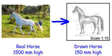
The whole idea behind creating scale drawings it to allow the drafter to create a drawing which is proportionately the same as the artifact it represents. Using a measuring device called a scale, we can create accurate drawings of both very large objects or very small objects and fit either on a standard size piece of paper.
2:1
Pronounced "Two is to One"
DOUBLE SIZE :2 millimeters on paper =1 millimeter on the artifact
The drawing is twice as large as the artifact.
1:1
Pronounced "One is to One"
FULL SIZE: 1 millimeter on paper =1 millimeter on the artifact
The drawing is the exact same size as the artifact.
1:2
Pronounced "One is to Two"
HALF SIZE : 1 millimeter on paper =2 millimeters on the artifact
The drawing is half the size of the artifact.
1:4
Pronounced "One is to Four"
QUARTER SIZE or 1 millimeter on paper= 4 millimeters on the drawing.
The drawing is one quarter the size of the artifact.
I've decided to post this because in our last drawing plate, we got confused on how we should write the scale 0.75:1. Click HERE if you want to take a look on my first drawing plate for this semester. I got an 85 for it. It's too low. Sad.
Friday, July 23, 2010
Kinematics - Displacement (Plate #1)
After three failures on my first plate, I've finished a decent one. The first try was acceptable since I made a mistake on the first steps in drawing the figure. The problem on the second try was in terms of the scale so it's not pain in the ass. And the last one was a failure of my ruler. The ruler that I'm using that time has a different dimension, an inch in my ruler is smaller than the real "inch", and thanks to my friend because he's the one noticed the glitch on my plate but I hope he saw it earlier before I'm totally finished drawing my plate. Maybe my ruler was fake. So beware of fake rulers, it will waste your precious time.
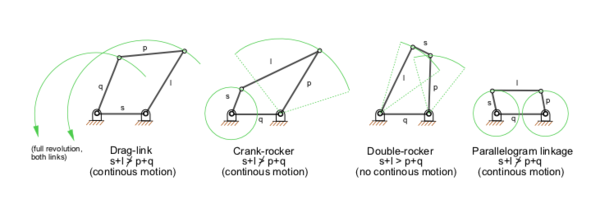
My first drawing plate for this sem is about four-bar linkage. A four-bar linkage is the simplest movable linkage. It consists of four rigid bodies called cranks and links, each attached to two others by single joints or pivots to form a closed loop. Four-bars are simple mechanisms common in Mechanical Engineering machine design and fall under Kinematics.
I've traced the ellipse like curve and the semi-circular curve using my FRENCH CURVE. I've spent a full 5 hours in finishing this first *take note, FIRST* plate. So join me on the upcoming head-aches. Just kidding.
Seriously, I'm having a hard time on my Kinematics. And I'm expecting a lot of trouble in the near future *fingers crossed* but I'm allotting more time in studying the course. Wish me a good luck.
| Photo courtesy of wikipedia.org |
![]() |
| First few lines were drawn. |
![]() |
| Finishing the oscillating crank. |
![]() |
| Final plate. |
I've traced the ellipse like curve and the semi-circular curve using my FRENCH CURVE. I've spent a full 5 hours in finishing this first *take note, FIRST* plate. So join me on the upcoming head-aches. Just kidding.
Seriously, I'm having a hard time on my Kinematics. And I'm expecting a lot of trouble in the near future *fingers crossed* but I'm allotting more time in studying the course. Wish me a good luck.
Wednesday, July 7, 2010
Kinematics- Velocity Analysis
Topics included in the hand-out:
1. Velocities and Acceleration of Mechanisms
a. Resolution and Composition
b. Instantaneous Axis of Velocity
c. Centro
d. Velocity Polygon or Relative Velocity
2. Short review of Vectors
3. Scales
a. Space Scale, Ks
b. Velocity Scale, Kv
c. Acceleration Scale, Ka
Click here to access the file:
Velocity Analysis
Our professor also gave the presentation for the course, Kinematics. Download it now.
Kinematics Presentation
1. Velocities and Acceleration of Mechanisms
a. Resolution and Composition
b. Instantaneous Axis of Velocity
c. Centro
d. Velocity Polygon or Relative Velocity
2. Short review of Vectors
3. Scales
a. Space Scale, Ks
b. Velocity Scale, Kv
c. Acceleration Scale, Ka
Click here to access the file:
Velocity Analysis
Our professor also gave the presentation for the course, Kinematics. Download it now.
Kinematics Presentation
Subscribe to:
Posts (Atom)