Here's my third plate. Like my second plate, it's about Velocity Analysis. I made this plate right after drawing the second one. It took me 2.5 hours to completely finish the plate. I had a hard time drawing it because the instantaneous axis of the links are too far, so I have to use a big compass. Here's the compass used by my classmate while making this plate.
Drawing after the cut.
Here's my third plate.
Check out the CAD version.
Showing posts with label Drawing. Show all posts
Showing posts with label Drawing. Show all posts
Thursday, August 12, 2010
Tuesday, August 10, 2010
Kinematics - Resolution and Composition (Plate #2)
My second plate is about Velocity Analysis using the resolution and composition method. Velocity analysis is a graphical technique used for the determination of the velocities of the parts of a mechanical device, specially those of a plane mechanism with rigid component links. It was the first lesson on my Kinematics class and my third plate is also about velocity analysis using the instantaneous axis method.
The drawing itself is not that hard but you need to be very careful in executing the steps. Analyzing the problem is much more difficult. The more complex the linkage are the harder it will be. My second plate isn't that complicated but it took me about 3 hours just to finish this plate and I hope I will get a high grade on it.
Drawing after the cut.
Here's my second plate.
Q2BBCQ4EFPS is a compound linkage. Q2 and Q4 are fixed centers on a horizontal line with Q4 7.5 inches to the right of Q2. Q2B, 3.5 inches long, oscillates above Q2. CQ4 is a crank 2 inches long that rotates about Q4. BC is a connecting rod 7 inches long. P is an oscillating bearing block that is pivoted at a fixed point 4.5 inches above Q4. EF, 8.5 inches long, which is pinned to the mid point of the connecting rod BC at E, extends through the oscillating block at P. F is connected to a slide 7 by a link FS, 6.5 inches long. The slide 8 moves in a vertical guide whose center line is 1.5 inches to the right of Q4. Q4C rotates uniformly counterclockwise at 30 rpm and has turned through an angle of 150 degrees from right horizontal position, causing S to be below Q2Q4.
The problem was retrieved from Elements of Mechanism by Doughtie and James, p.471 - L-8.
Sunday, August 1, 2010
Kinematics - Instantaneous Axis CAD (Plate #3)
Given the linkage Q2BCQ4EFH. Q2 and Q4 are fixed centers lying horizontally 6 in. apart with Q2 to left of Q4. Q2B is a crank 3 in. long and CQ4E is a lever 8 in. long pivoted at its mid point Q4, with C oscillating above the center line Q2Q4. BC is a connecting rod 7 in. long. EF is a link 8.5 in long driving a sliding block 8 and pinned to 8 at F, which moves along a horizontal line through Q2Q4 and to the right of Q4. MH and NH are links 2 in. long pinned to links EQ4 and EF, respectively, 2 in. from E. These link are pinned at H within the acute angle Q4EF. Q2B rotates counterclockwise at 30 rpm.
The problem was retrieved from Elements of Mechanism by Doughtie and James, p.470 - L-6.
Click to enlarge |
I have drawn the figure using AutoCAD 2010. The main figure is colored black and the red one shows its extremity. The phantom line, colored as magenta, represents the extreme ends of the lever CQ4E as it oscillates.
Unfortunately, I wasn't able to finish the solution yet. I'm going to update this post whenever I confirmed my solution. If you see corrections on the figure, kindly throw a comment below. I hope this helps.
Saturday, July 31, 2010
Winnie the Pooh with Tigger by Jep
Believe it or not, this was a result of my creativity and boredom about 5 years ago. The times where I'm still fond of sketching figures. I cannot exactly remember why I ended up drawing Pooh and Tigger but at least they are here now. I'll share to you how I made them.
I started drawing Pooh and Tigger on a piece of paper, at the back of a scratch paper (as I've said it was a result of boredom). Luckily, I was able to save it from being crumpled and thrown in to a trashcan. Then after some time, I decided to put some colors on it and to practice my Photoshop skills; so I took a picture of it using our digital camera since our scanner has stopped working. The black and white version on the upper right hand corner was my original drawing. Finally, I edited the picture on Adobe Photoshop using the skills and techniques learned from self-exploration and computer subjects.
This is the only drawing that I have edited and added colors on it. I will find time to look for my other drawings and will try to share those too.
What can you say?
Tuesday, July 27, 2010
The Drawing Scale
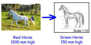
The whole idea behind creating scale drawings it to allow the drafter to create a drawing which is proportionately the same as the artifact it represents. Using a measuring device called a scale, we can create accurate drawings of both very large objects or very small objects and fit either on a standard size piece of paper.
2:1
Pronounced "Two is to One"
DOUBLE SIZE :2 millimeters on paper =1 millimeter on the artifact
The drawing is twice as large as the artifact.
1:1
Pronounced "One is to One"
FULL SIZE: 1 millimeter on paper =1 millimeter on the artifact
The drawing is the exact same size as the artifact.
1:2
Pronounced "One is to Two"
HALF SIZE : 1 millimeter on paper =2 millimeters on the artifact
The drawing is half the size of the artifact.
1:4
Pronounced "One is to Four"
QUARTER SIZE or 1 millimeter on paper= 4 millimeters on the drawing.
The drawing is one quarter the size of the artifact.
I've decided to post this because in our last drawing plate, we got confused on how we should write the scale 0.75:1. Click HERE if you want to take a look on my first drawing plate for this semester. I got an 85 for it. It's too low. Sad.
Friday, July 23, 2010
Kinematics - Displacement (Plate #1)
After three failures on my first plate, I've finished a decent one. The first try was acceptable since I made a mistake on the first steps in drawing the figure. The problem on the second try was in terms of the scale so it's not pain in the ass. And the last one was a failure of my ruler. The ruler that I'm using that time has a different dimension, an inch in my ruler is smaller than the real "inch", and thanks to my friend because he's the one noticed the glitch on my plate but I hope he saw it earlier before I'm totally finished drawing my plate. Maybe my ruler was fake. So beware of fake rulers, it will waste your precious time.
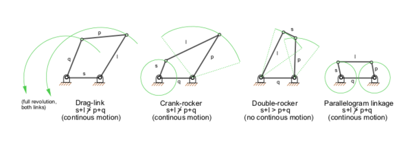
My first drawing plate for this sem is about four-bar linkage. A four-bar linkage is the simplest movable linkage. It consists of four rigid bodies called cranks and links, each attached to two others by single joints or pivots to form a closed loop. Four-bars are simple mechanisms common in Mechanical Engineering machine design and fall under Kinematics.
I've traced the ellipse like curve and the semi-circular curve using my FRENCH CURVE. I've spent a full 5 hours in finishing this first *take note, FIRST* plate. So join me on the upcoming head-aches. Just kidding.
Seriously, I'm having a hard time on my Kinematics. And I'm expecting a lot of trouble in the near future *fingers crossed* but I'm allotting more time in studying the course. Wish me a good luck.
 |
| Photo courtesy of wikipedia.org |
 |
| First few lines were drawn. |
 |
| Finishing the oscillating crank. |
 |
| Final plate. |
I've traced the ellipse like curve and the semi-circular curve using my FRENCH CURVE. I've spent a full 5 hours in finishing this first *take note, FIRST* plate. So join me on the upcoming head-aches. Just kidding.
Seriously, I'm having a hard time on my Kinematics. And I'm expecting a lot of trouble in the near future *fingers crossed* but I'm allotting more time in studying the course. Wish me a good luck.
Thursday, July 22, 2010
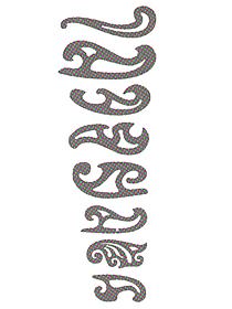
The French Curve
 The use of french curve is to draw a smooth curve through predetermined points. So after plotting the points, a light pencil line should be sketched to connect the points in a smooth flowing curve. In able to draw the finished line over the freehand line, match the various parts of the french curve to various segments of the freehand curve.
TIPS:
1. Avoid abrupt changes in curvature by placing the short radius of the french curve toward the short radius portion of the line to be drawn.
2. Change your position around the drawing board when necessary so that you can work on the side of the french curve that is away from you.
3. You should avoid working on the "under" side of the french curve.
4. Place the french curve so that it intersects at least two points of the curve. 3 points is always recommended.
5. When drawing the curve along the edge of the french curve, stop short of the last point intersected. Then move the french curve along to intersect two or three more points.
6. Make sure that the edge of the curve connects smoothly with the part of the curve that is already drawn.
7. When drawing irregular curves, you can draw a perfectly smooth curved line by plotting enough points and by drawing in short steps.
The figure above shows how a smooth curve is draw through a series of plotted points.
- The french curve in view A matched points 1, 2, 3, and 4. Draw a curve from 1 to 3 only.
- At B, the curve matches points 3 to beyond 4. Draw a curve from 3 to 4 only.
- At C, it matches points 4, 5, and 6. Draw a curve from 4 to just short of 6.
- At D, it matches a point short of 6 to beyond 7. Draw a curve from 6 to 7.
- At E, it matches a point short of 7 to beyond 9. Draw a curve from 7 to 9.
- At F, it matches a point short of 9 to beyond 11. Draw a curve from 9 to 11.
You will probably notice how the french curve is turned over and reversed to find portions that fit the points on the line with increasing or decreasing changes in the curvature.
Here are my Rotring french curves that I use in my drawing plates. They are quite new. I've bought them Wednesday this week in order to finish a plate because I need to trace an irregular ellipse. By the way, if you wanted to learn how to draw an ellipse, click HERE.
Tuesday, July 6, 2010
How to Draw an Ellipse by Four-Center Method
There are various methods in drawing an ellipse. We have the simple Pins & Strings method, the Concentric-circle method, and the Four-center method. I will share to you the Four-center method by giving the steps and a diagram so it will be easier to understand.
Steps:
1. Draw the major axis, AB, and the minor axis, CD, which are mutually perpendicular at the midpoint, O, as shown in the diagram.
2. Draw AD, that connects the end points of the two axes.
3. Using a compass, point the tips of it to DO then plot it along AO and reset the compass on the remaining distance to O.
4. With the difference of semiaxes thus set on the dividers, mark off DE equal to AO minus DO.
5. Draw perpendicular bisector AE, and extend it to intersect the major axis at K and the minor axis at H.
6. With the compass, mark off OM equal to OK, and OL equal to OH.
7. With H as a center and radius R1 equal to HD, draw the bottom arc.
8. With L as a center and the same radius as R1, draw the top arc.
9. With M as a center and the radius R2 equal to MB draw the end arc.
10. With K as a center and the same radius as R2, draw the other end arc.
The four circular arcs thus drawn meet, in common points of tangency, P, at the ends of their radii in their lines of centers.
If you have questions or request, feel free to leave a comment.
Monday, July 5, 2010
Lateral Development
The development of lateral surfaces is simply the flat surface or 2D that you need to cut when you are about to make a 3D thing. If you want to make a cylinder, pyramid, or a cube for an instance a lateral development layout may firstly be required.
(Click to enlarge)
 Here is an example of a lateral development drawing of a rectangular right pyramid. The true lengths of the edges and base are measured in order to have an accurate piece. A top view and front view of the pyramid was drawn first to help in drafting the lateral development of it.
Actually lateral developments are very useful in my machine shop course. In my class, we are about to make a tool box as our first project for the semester and a layout of it should be draft first.
(Click to enlarge)
 Here is an example of a lateral development drawing of a rectangular right pyramid. The true lengths of the edges and base are measured in order to have an accurate piece. A top view and front view of the pyramid was drawn first to help in drafting the lateral development of it.
Actually lateral developments are very useful in my machine shop course. In my class, we are about to make a tool box as our first project for the semester and a layout of it should be draft first.
(Click to enlarge)
This is the draft of our group. The tool box layout is divided into five parts. The holder and the lowest piece under the lock will be attached to the cover and the upper pieces of the lock will be on the body. The connector will be used to attach the two main parts of the tool box, the cover and the body.
Subscribe to:
Posts (Atom)


